
For the seasoned manufacturing quality professional, First Article Inspection (FAI) is a familiar process performed after the first production run of a new or redesigned part. But for those outside of or newer to the quality profession, the requirements of FAI may provoke a lot of questions and uncertainty.
In short, FAI is the process of planning, conducting and reporting the verification of a production process. This verification “closes the loop” between the customer’s expectations — usually described on the part’s engineering drawing — and the actual output of the supplier’s process.
While not explicitly stated as a requirement in any of the major quality systems standards, forging companies are often required by their customers’ requirements to perform FAI. For forgers supplying to the aerospace and defense industries for instance, the AS9102B standard provides guidance on how to perform an FAI and complete the First Article Inspection Report (FAIR) that many of their customers require.
For forgers supplying to the automotive industry, IATF-16949 similarly does not state a requirement for the use of FAI. But it does specify the use of the Automotive Industry Action Group’s (AIAG) Production Part Approval Process (PPAP) when launching new parts and processes. Two of PPAP’s 18 major requirements include the Dimensional Inspection report and the Material Test report. The verifications performed while completing these reports essentially fulfill the intent of FAI. And for those companies complying with the requirements of ISO-9001, FAI is a convenient way to “… verify that the product and service requirements have been met”1 according to section 8.6 titled Release of products and services.
But regardless of any external requirements, FAI helps manufacturers assure themselves that there won’t be any “surprises” after their new parts ship.
FAI begins with the customer’s requirements, usually communicated in the form of an engineering drawing. Engineering drawings contain a part’s dimensions, raw material requirements, and special processes like heat treatment or plating. They may also specify a supplier’s adherence to customer- or industry-specific quality standards such as the American Society for Testing and Materials (ASTM) A105, which applies to forging used in piping applications.2
A quality engineer or technician can begin planning this verification process long before receiving the actual parts by ballooning the part print. Ballooning refers to the placement of circled numbers nearby every part requirement as shown in Figure A.
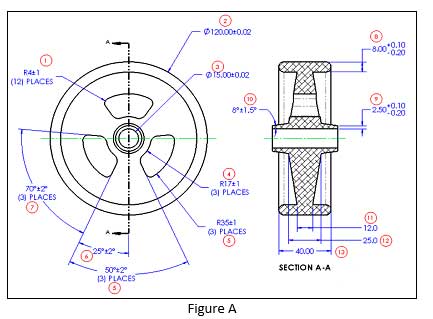
This includes all dimensions, processes, second- or third-party standards, etc. The rule for veteran quality techs is, “If in doubt, throw a balloon on it.” Since complex forgings could have hundreds of dimensions and requirements, software programs are available to automate or at least simplify the ballooning process.
The next step toward completing an FAI is to then transcribe each part requirement along with its ballooned number onto a dimensional inspection report sometimes called an Initial Sample Inspection Report (ISIR). These worksheets are typically assembled in Microsoft Excel, but again, specialized software programs may aid in this step as well. Figure B shows a typical dimensional inspection report.
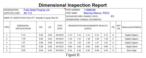
Below the report’s main header containing part and supplier information, column headers commonly include: item number (from the ballooned drawing), nominal dimension, plus tolerance, minus tolerance, measured values, measurement tool/ method, and pass/fail.
In preparation to receive the production samples, layout technicians can fill in the first few columns of this report with the ballooned numbers, part dimensions, and parts tolerances. Off-print specifications like conformance to customer- or industry-specific standards can simply be listed under the “Dimension / Specification” column with the adjacent tolerance columns left blank.
Also prior to receiving forged samples, a layout technician may begin thinking through which measurement tools would best address each dimensional characteristic. Often, forged parts have relatively wide dimensional tolerances that would allow for the use of hand tools such as calipers and height gages. But, given the ubiquity of Coordinate Measuring Machines (CMM’s) and the pre-programmability and automation they offer, technicians may choose this higher accuracy device instead.
A major key to an FAI’s usefulness is found in the initial production process itself. All manufacturers, at times, are trying to squeeze the most out of their project plans, but get side-lined by problems like late tooling, unexpected downtime, or shifting priorities. And in these sometimes-chaotic product launches, manufacturing professionals may be tempted to “cut corners” but substituting presses, tools or materials in an attempt to meet their timing commitments. But this is a recipe for trouble. For an FAI to accurately depict the production process and maybe even expose its weaknesses early enough to react to them, the process used to produce the FAI samples must be complete. The machines, tools, people and gages that are planned for use in mass production have to be in place when the FAI samples are drawn. Rushing samples through an incomplete process only exposes the forger to risks that could readily be avoided.
At this point, the inspection professional is ready to measure samples, or articles, from the initial production run. And even though First Article Inspection implies that the samples measured are the very first ones produced, that is not typically the case. In most cases, the samples measured for the FAI – typically 3 to 10 part — are either drawn randomly or systematically (i.e., beginning, middle, end) from the entire first production run. This allows the resulting measurements to depict the expected variation across a production run and not just from a small segment of it. Exceptions to this include cases where single forgings are large and expensive, or when the expected production runs are relatively small.
Measurement professionals performing the FAI are expected to follow best practices, assuring their chosen instruments are functioning correctly, within their calibration intervals, and traceable to a recognized standard. The layout technician then measures each ballooned feature on each sample and enters their measurement results into the dimensional inspection report. See figure B.
In addition to the dimensional measurements, other professionals may contribute to the FAI as well. For instance, a metallurgist may need to perform a hardness and microstructure analysis to assure the forging meets its heat treatment requirements. Or a quality engineer may need to review external quality standards cited on the engineering drawing to assure those requirements are met as well. The results of their analyses are also recorded on the dimensional inspection report or associated documents.
The final step to completing an FAI is a careful review, typically conducted by a quality engineer or manager, prior to submitting it to the customer. Asking questions like these can help spot common problem areas:
- Have all the part characteristics been addressed?
- Have all the dimensions and tolerances been accurately transferred to the dimensional inspection report?
- Are the chosen measurement tools appropriate for the dimensional tolerance?
- Were any of the measured characteristics outside the specification limits?
- How will outside-the-specification characteristics be addressed?
- How close are these observed values to the specification limits?
- Are any individual samples significantly different than the others?
- Are the microstructure photos clear enough for the customer’s interpretation?
When a first article inspection is performed by experienced technicians, with suitable tools and methods, on appropriately selected samples, everyone benefits. The supplier understands the outputs of their process, and the customer knows what they can expect to receive. FAI not only reduces the “surprises” that often accompany new product launches, but offers both parties reasonable assurance that the customer’s part is a reasonable fit with the supplier’s process.
References:
- International Organization for Standardization. (2015) Quality Management Systems – Requirements (ISO standard no. 9001:2015).
- American Society for Testing and Materials. (2021) Standard Specification for Carbon Steel Forgings for Piping Applications (ASTM A105/A105M-21).
Author’s Biography:
Ray Harkins is the Quality and Technical Manager for Ohio Star Forge in Warren, Ohio. He earned his Master of Science from Rochester Institute of Technology and his Master of Business Administration from Youngstown State University. He also teaches manufacturing and business-related skills through the online learning platform, Udemy. He can be reached via LinkedIn at linkedin.com/in/ray-harkins or by email at rharkins@ohiostar.com.
Click on the following coupon codes to receive substantial discounts on his courses, or reach out to him via LinkedIn at linkedin.com/in/ray-harkins or by email at the.mfg.acad@gmail.com.
Reliability Engineering Statistics: https://www.udemy.com/course/reliability-engineering-statistics/?referralCode=C8CF07ACDEDF252A7C51
An Introduction to Reliability Engineering
An Introduction to Quality Engineering